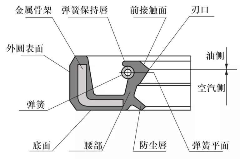
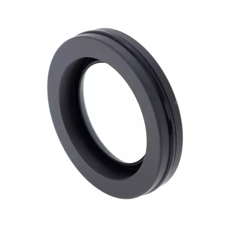
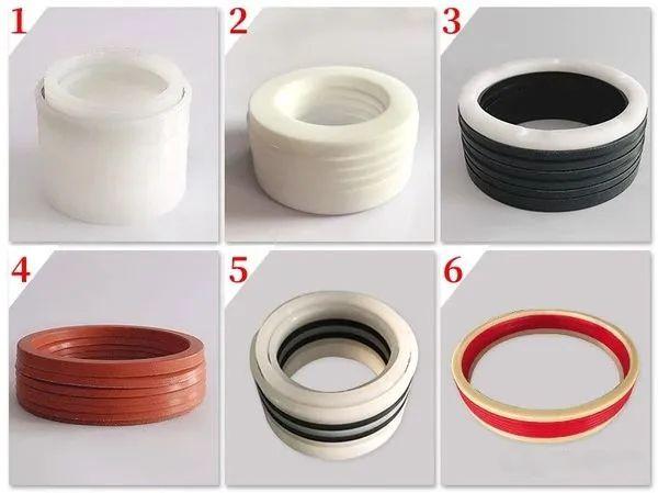
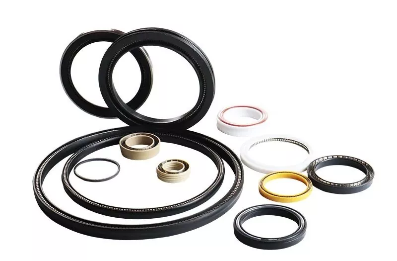
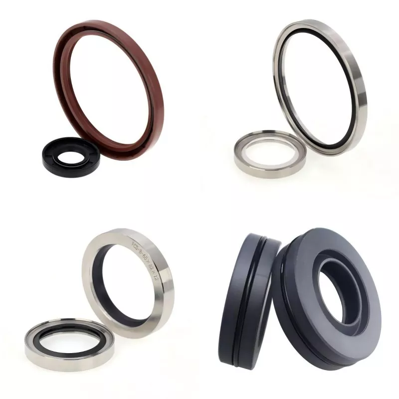
Rotary shaft lip seals are commonly known as oil seals. They are installed in rotary bearing housings and undergo relative motion against the rotating shaft. A metal insert provides structural support, while a garter spring applies radial preload to the sealing lip, preventing lubricant leakage and the ingress of external contaminants.
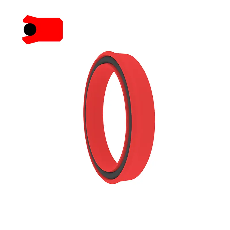
Schematic of common oil seal cross-sections
Installation design and requirements
1. Shaft material: Commonly carbon steel or stainless steel. For high-speed applications, chrome plating is used, with a hardness of HRC 40–45.
2. Rotary shaft and housing bore design: The shaft surface must be smooth and free of burrs. Spiral machining marks can create a pumping effect leading to leakage; therefore, it is recommended to grind the shaft area where the seal is installed to a surface roughness of Ra 0.1–0.5 μm. A smoother finish is required as rotational speed increases.
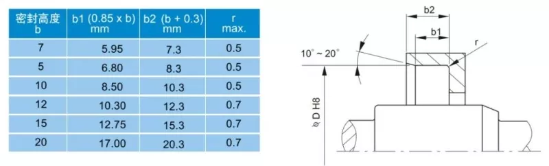
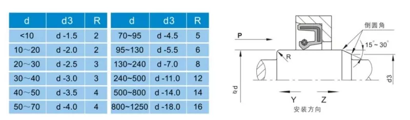
To facilitate installation and removal, the shaft and housing bore must be designed with chamfers or rounded edges, as shown in Figures 1 and 2.
Figure 1: Housing bore chamfer design
Figure 2: Rotary shaft chamfer design
Factors affecting rotary shaft lip seal performance
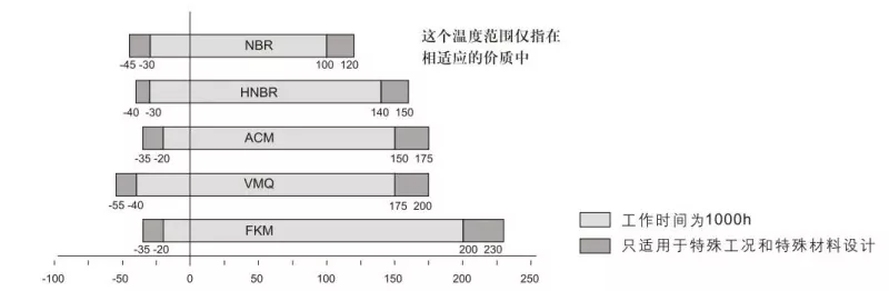
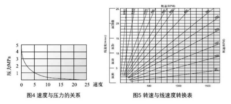
There are numerous factors influencing sealing performance. Beyond the oil seal's own material and structure, factors such as the medium, temperature, pressure, lubrication, speed, and surface roughness directly impact performance—and these factors often interact with one another. The following charts are provided for user reference.
Figure 3: Effect of temperature on oil seals
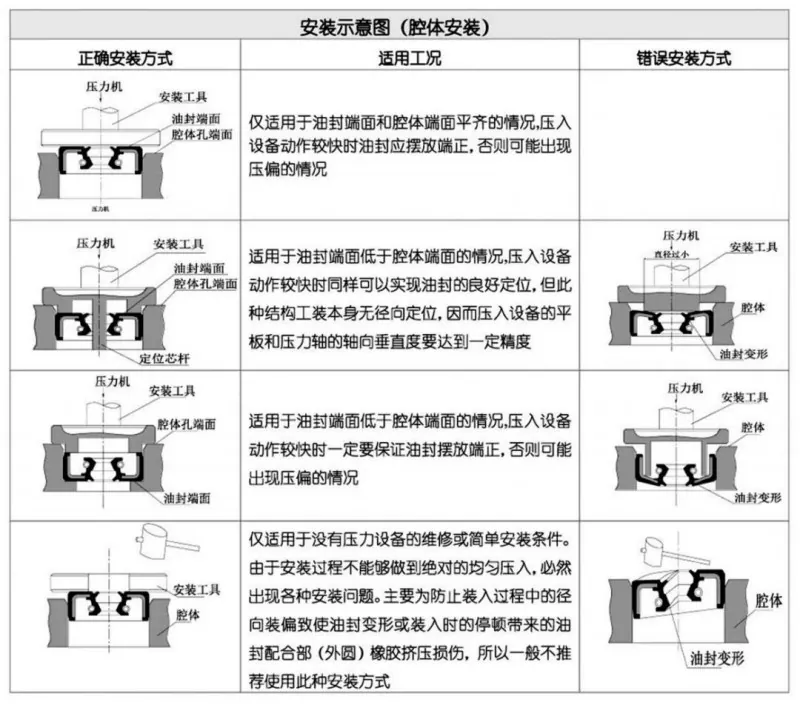
Oil seal installation
Careful installation is a prerequisite for the proper functioning of an oil seal.
We use cookies to offer you a better browsing experience, analyze site traffic and personalize content. By using this site, you agree to our use of cookies.Privacy Policy